
Carrier-in-Carrier Satellite Links: How CnC Actually Works
Calculate Carrier-in-Carrier satellite bandwidth savings, then verify modem compatibility, transparent-payload loopback, power ratios, commissioning, and ROI.
What changed: Rebuilt the guide around the exact overlap calculation, power-versus-bandwidth limits, product-specific eligibility, commissioning evidence, and same-scope ROI; removed universal cancellation depth, pricing, breakeven, payback, latency, equipment, and savings claims.
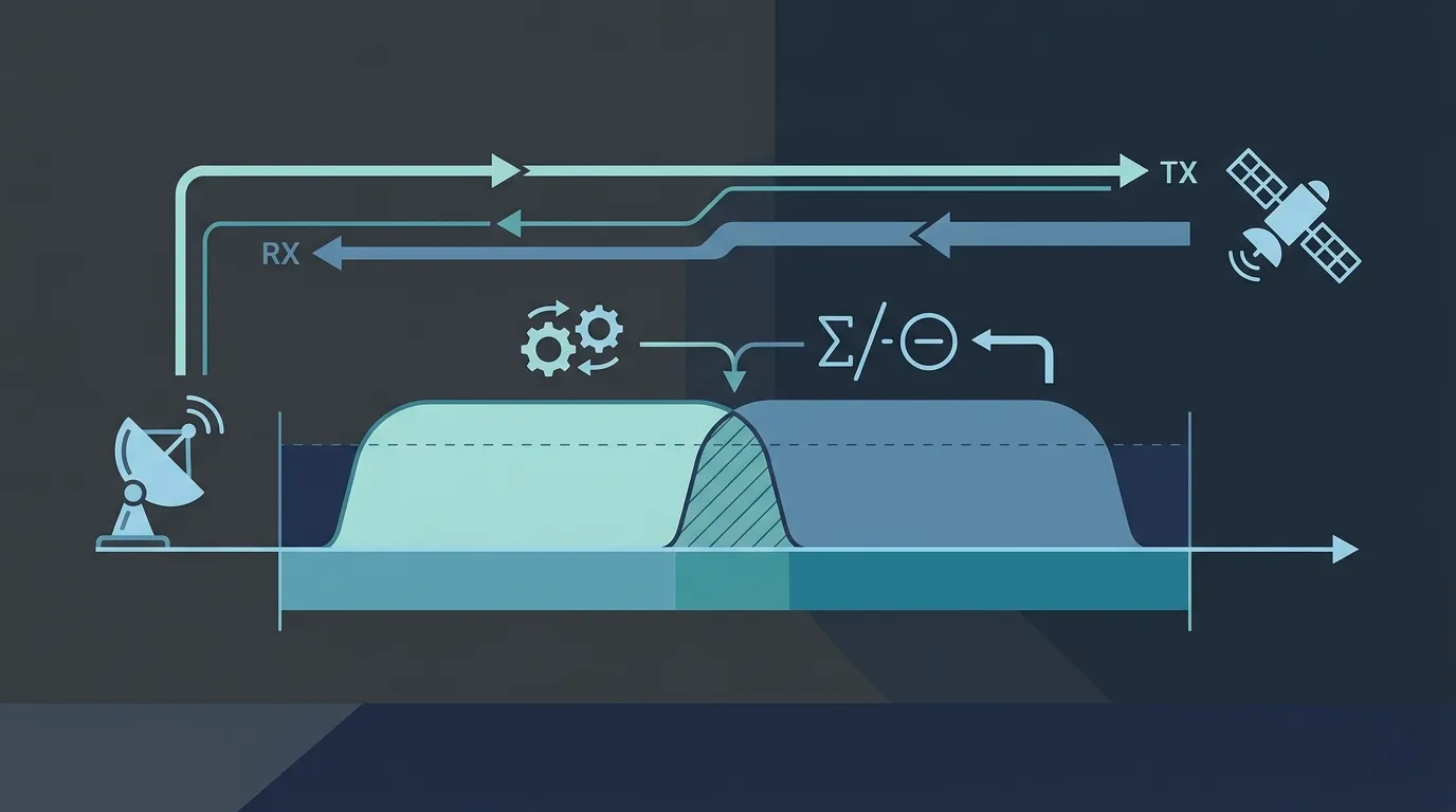
Carrier-in-Carrier satellite links place two opposite-direction carriers in overlapping spectrum and use adaptive self-interference cancellation at each end. The best-case bandwidth reduction is easy to calculate, but a safe design also has to pass modem, payload, power, link-margin, acquisition, operator, and commercial checks.
This page uses Carrier-in-Carrier (CnC) and DoubleTalk Carrier-in-Carrier for Comtech's branded implementation. It is a product feature, not an open interoperability standard or a capability implied by the words “satellite modem.” Confirm the exact modem pair, software, feature licenses, supported waveforms, satellite path, and operator frequency plan before treating a calculation as deployable.
Scope note: Organization fact check updated 26 August 2026 against the primary vendor documents listed on this page. The detailed numerical limits in the older CDM-625A data sheet are model-specific examples, not current universal CnC limits. This review is not a named expert approval, satellite-operator authorization, or substitute for the current product manual and witnessed link acceptance.
Transponder Bandwidth | Symbol Rate and Roll-Off | Link Budget Guide
Quick Answer
In a supported CnC link, each receiver gets a composite containing the wanted far-end carrier and its own carrier after that carrier has passed through the satellite path. The modem already knows its local transmit waveform. It estimates how the returned copy has been delayed, frequency-shifted, phase-rotated, and scaled, then subtracts the estimate before demodulating the wanted carrier.
For the implementation documented in the legacy CDM-625A data sheet, the transmitting station must be able to receive its own signal through a non-processing satellite channel. A payload that demodulates and remodulates the signal can break that assumption. Do not generalize this requirement to an undocumented product; obtain the exact compatibility statement for the selected modem and payload.
If carriers with occupied spans B_A and B_B overlap by O, the geometric saving is:
B_separate = B_A + B_B
B_overlap  = B_A + B_B - O
saving     = O
saving %   = O / (B_A + B_B) × 100
The overlap cannot exceed the smaller carrier. With full overlap:
O_max          = min(B_A, B_B)
B_overlap,min  = max(B_A, B_B)
maximum saving = min(B_A, B_B) / (B_A + B_B) × 100
That percentage is a frequency-span upper bound, not a guaranteed reduction in leased capacity or monthly cost.
How the Cancellation Works
The 2010 Comtech DoubleTalk white paper describes an adaptive process with these inputs and estimates:
- The local modem supplies a copy of the waveform it is transmitting.
- The receiver observes the composite returned through the satellite.
- The canceller estimates delay, frequency offset, phase or complex gain, and their variation over time.
- It builds an estimate of the returned local carrier and subtracts it from the composite.
- The normal receiver processes the residual wanted carrier from the far end.
This explains why simply tuning two ordinary modems to the same frequency does not create CnC. The receiver needs a supported cancellation implementation and enough information about the local transmit signal and returned path to maintain the estimate.
The white paper reports cancellation results for historical Comtech products. Those results are vendor-reported product performance, not a universal cancellation-depth promise. Acceptance should instead be based on the current manual's allowed envelope and measured end-to-end degradation for the purchased configuration.
Calculate the Spectrum Saving
Full-Overlap Upper Bounds
Assume the carriers can be fully aligned and ignore guard-band, channel-grid, power, and product constraints for the moment.
| Carrier bandwidth ratio | Separate span | Full-overlap span | Geometric saving |
|---|---|---|---|
| 1:1 | 2B | B | 1/2 = 50.00% |
| 2:1 | 3B | 2B | 1/3 = 33.33% |
| 5:1 | 6B | 5B | 1/6 = 16.67% |
| 10:1 | 11B | 10B | 1/11 = 9.09% |
For example, let B_A = 2.4 MHz and B_B = 1.2 MHz:
B_separate = 2.4 + 1.2 = 3.6 MHz
B_overlap  = max(2.4, 1.2) = 2.4 MHz
saving     = 3.6 - 2.4 = 1.2 MHz
saving %   = 1.2 / 3.6 × 100 = 33.33%
The arithmetic is exact for the stated spans and full-overlap assumption. It does not prove that this carrier pair is supported.
Partial Overlap
If only 0.8 MHz of the same pair can overlap:
B_overlap = 2.4 + 1.2 - 0.8 = 2.8 MHz
saving %  = 0.8 / 3.6 × 100 = 22.22%
Use occupied or allocated spans on the same basis. Do not mix information rate, symbol rate, nominal channel width, occupied bandwidth, and spectrum-analyzer resolution bandwidth. See Symbol Rate and Roll-Off for those conversions.
Why the Invoice May Not Fall by the Same Percentage
The frequency geometry omits several commercial and RF constraints:
- roll-off and emission-mask treatment;
- guard bands and operator channel-grid rounding;
- the overlap actually approved by the satellite operator;
- minimum lease increments or a fixed contractual commitment;
- transmit power, power-equivalent bandwidth, and transponder loading;
- the MODCOD or FEC change needed to restore link margin;
- capacity that is freed technically but cannot be removed from the contract.
Only capacity that can be released, avoided, or productively reassigned has economic value.
Bandwidth-Limited and Power-Limited Designs
Overlapping the carrier spectra does not make either transmitted RF carrier disappear. The satellite still receives and retransmits the composite energy. A link can therefore save frequency span while remaining constrained by transponder power, spectral-density limits, intermodulation, or required receive margin.
The legacy vendor white paper illustrates a planning method in which:
overlapped allocated bandwidth = max(BW_A, BW_B)
combined power-equivalent bandwidth = PEB_A + PEB_B
planned leased bandwidth = max(overlapped bandwidth, combined PEB)
This is a vendor planning model, not a universal operator billing rule. Use the operator's definitions and link-budget template. Iterate the waveform, code rate, symbol rate, EIRP, receive C/N0 or Es/N0, degradation allowance, and transponder operating point until both directions pass.
At minimum, preserve these quantities for each end:
| Quantity | Why it matters |
|---|---|
| Wanted-carrier level and margin | The wanted demodulator still has to meet its threshold after implementation loss |
| Returned self-carrier level | The canceller must track it within the supported power-density range |
| Power spectral-density ratio | Each site sees a different wanted-to-self relationship |
| Symbol-rate or bandwidth ratio | Product support can be narrower than the geometric overlap permits |
| Satellite operating point | The composite must remain within operator power, linearity, and emission limits |
| Fade and power-control range | A clear-sky setting may leave the supported cancellation envelope during a fade |
C/N, C/N0, Es/N0 and Eb/N0 explains how to keep the receive metrics on a common reference basis.
Product Evidence: Current Availability vs Legacy Limits
Product family and document date matter. The available public documents do not support one universal CnC specification.
| Evidence | What it establishes | What it does not establish |
|---|---|---|
| Current SLM-5650B data sheet | Carrier-in-Carrier is sold as a FAST option in listed data-rate tiers up to 70 Mbps | The complete CnC operating envelope, every waveform combination, or compatibility with another modem |
| Current SLM-5650B data sheet | Asymmetric transmit/receive data rate is listed as a separate FAST option | That buying CnC automatically enables every asymmetric configuration |
| Legacy CDM-625A data sheet | For that model: satellite loopback and a non-processing payload are required; the sheet lists delay, PSD-ratio, symbol-rate-ratio, and degradation limits | Current SLM-5650B limits or a rule for every CnC implementation |
| December 2010 white paper | Historical algorithm description, link-budget method, and baseline/overlap test sequence | A current service guarantee or an operator approval |
For context, the CDM-625A sheet lists 0–330 ms delay, a maximum 3:1 symbol-rate ratio in either direction, modulation-dependent PSD-ratio ranges, and specified degradation figures. Those numbers belong to that legacy model and configuration. They should be used to understand the kind of envelope a designer must check, not copied into a current procurement specification.
Ask the selected vendor for the current product manual, approved feature combination, option keys, software version, release notes, and interoperability statement. If the two sites use different modem models or vendors, require an explicit supported pairing and a witnessed test; do not infer cross-vendor interoperability from the term CnC.
Eligibility Gates Before Design Approval
A proposed carrier pair should pass every gate below before frequencies are overlapped on an operational transponder.
- Supported modem pair: exact hardware, software, data-rate options, cancellation license, waveform, FEC, framing, pilots, and interface modes.
- Returned local signal: documented satellite loopback through a payload type supported by the implementation.
- Approved frequency plan: written operator approval for center frequency, occupied bandwidth, polarization, EIRP or PSD, guards, and activation sequence.
- Supported carrier relationship: symbol-rate ratio, PSD ratio, delay, frequency offset, and modulation combination inside the current product limits at both sites.
- Complete link budgets: both directions pass in clear sky and the required propagation conditions, including documented cancellation or implementation degradation.
- Transponder compatibility: composite power, back-off, linearity, spectral mask, adjacent-carrier impact, and monitoring limits accepted by the operator.
- Acquisition and recovery: cold start, loss of the far-end carrier, frequency or power excursions, fade recovery, and modem switchover behave safely.
- Fallback plan: separate-frequency assignments or another approved rollback can restore service if cancellation cannot be acquired or maintained.
Failing one gate is not fixed by a large theoretical spectrum saving.
Commissioning and Acceptance Procedure
The legacy white paper's useful operational principle is to measure a non-overlapped baseline before judging the overlapped state. Adapt the exact sequence to the current manuals and the satellite operator's line-up procedure.
1. Approve the Test Plan
Record modem models, serial numbers, software, license keys, waveforms, symbol rates, occupied bandwidths, frequencies, powers, expected PSD ratios, link-budget thresholds, rollback frequencies, operator contacts, and pass/fail limits.
2. Establish the Conventional Baseline
Place the two carriers on approved non-overlapping frequencies with CnC disabled. At both sites record:
- transmit power and frequency;
- receive level,
C/N0,Es/N0orEb/N0on a defined estimator; - frequency error and symbol-rate state;
- BER, packet loss, throughput, and application result where applicable;
- spectrum plots with documented reference level, span, RBW, VBW, detector, and averaging;
- modem alarms and operator monitoring observations.
3. Move to the Approved Overlap
Follow the operator's coordinated sequence. Do not place unapproved co-channel carriers on a live transponder. Confirm composite power and spectrum before enabling traffic at the final operating point.
4. Enable Cancellation and Measure Degradation
At each end, verify acquisition and stable cancellation. Compare wanted-carrier performance with the baseline using the same estimator and traffic conditions:
measured degradation = baseline metric - overlapped metricDefine the sign and metric in the test plan. A spectrum display alone is insufficient: the composite can look plausible while the demodulator margin or packet performance fails.
5. Exercise Faults and Boundaries
Test far-end carrier loss and return, local reboot, power step, frequency offset, fade or attenuator steps, traffic-load changes, redundancy switchover, alarm delivery, and rollback. Hold each condition long enough to observe acquisition, stability, errors, and recovery.
6. Close With Operator Evidence
Retain approved as-built frequencies and powers, baseline and CnC results, screenshots, modem exports, operator acceptance, alarm thresholds, rollback instructions, and named operational owners. A successful lab demonstration does not replace satellite-path acceptance.
Operations and Failure Behavior
When two carriers are co-channel, loss of cancellation can expose the wanted receiver to strong returned self-interference. The design needs an observable state and a safe recovery path, not only a green light at commissioning.
Monitor, where the product exposes them:
- cancellation acquisition or lock state;
- estimated delay, frequency offset, and relative carrier level;
- wanted-carrier
C/N0,Es/N0orEb/N0on the declared estimator; - BER, FEC status, packet loss, throughput, and application health;
- transmit power, receive level, frequency, and modem alarms;
- operator spectrum or transponder alarms;
- redundancy state, software version, and feature-license state.
Time-correlate both sites and operator telemetry. A single metric cannot distinguish cancellation loss from rain attenuation, uplink power error, transponder interference, oscillator drift, traffic congestion, or a terrestrial failure.
For a redundant modem design, verify that the standby unit has the required option keys and compatible configuration, and test whether cancellation reacquires within the service recovery objective. “1+1 modem” does not by itself prove hitless CnC recovery.
Build a Defensible ROI Model
Do not use a universal “more than 2 MHz” threshold or a fixed six-to-eighteen-month payback. The answer changes with the removable lease increment, contract, modem options, engineering effort, spares, and power constraint.
Use dated quotes and the same evaluation term:
monthly capacity value
  = removable leased MHz × price per MHz-month

net monthly benefit
  = monthly capacity value
  + value of usable reassigned capacity
  - incremental recurring cost

payback months
  = incremental one-time cost / net monthly benefit
Payback is defined only when net monthly benefit > 0. Do not count the same freed capacity once as avoided lease cost and again as reassigned value.
Include at least:
- modem, license, software, interface, and redundancy differences;
- engineering, lab, line-up, operator, installation, and acceptance work;
- spares, support, training, monitoring, and future software maintenance;
- lease rounding, minimum commitment, contract term, and change charges;
- link-budget changes, extra power cost, or capacity needed to recover margin;
- scheduled outage, rollback reservation, and operational-risk allowance;
- tax, shipping, customs, and field-service costs where applicable.
Run downside cases for partial rather than full overlap, no immediate lease reduction, lower price per MHz, added power-equivalent bandwidth, and a modem replacement during the term. Report the assumptions beside the result.
Relationship to SCPC, TDMA, ACM, and Frequency Reuse
CnC is a cancellation function, not an access method. It is commonly discussed for a paired continuous-carrier link, but support depends on the exact waveform and modem implementation. Do not infer that an arbitrary SCPC or TDMA carrier can use it.
Adaptive coding and modulation changes the waveform in response to channel conditions. CnC and ACM are conceptually separate, but successful combination requires explicit product support for the allowed modes and transitions. The current SLM-5650B sheet lists Carrier-in-Carrier, asymmetric TX/RX, and other waveform features as options; listing them on one product does not prove every combination is enabled or supported.
CnC also differs from spatial or polarization frequency reuse. Frequency reuse separates same-frequency signals by beam, polarization, geography, or another isolation mechanism. CnC deliberately receives the returned local signal and removes it with adaptive cancellation. A system may use both concepts, but their interference and acceptance analyses remain separate.
Decision Worksheet
| Decision field | Required evidence | Result |
|---|---|---|
| Exact carrier spans and overlap | Symbol rate, roll-off, allocation basis, operator plan | |
| Geometric saving | O / (B_A + B_B) with assumptions | |
| Billable capacity change | Current lease, rounding, PEB rule, contract amendment | |
| Modem eligibility | Models, software, licenses, feature-combination statement | |
| Satellite-path eligibility | Loopback and payload-processing confirmation | |
| Carrier envelope | Delay, PSD ratio, rate ratio, waveform, offset limits | |
| Link margins | Both-direction baseline and CnC budgets | |
| Operator acceptance | Power, spectrum, line-up, and written approval | |
| Failure recovery | Alarm, rollback, reacquisition, and redundancy tests | |
| Economics | Dated one-time and recurring same-scope costs |
Treat unknown mandatory fields as open risks, not as zero-cost assumptions.
Frequently Asked Questions
What is Carrier-in-Carrier in satellite communication?
It is a supported modem function that overlaps two opposite-direction carriers and cancels the known returned local waveform at each receiver so the wanted far-end carrier can be demodulated. This page discusses Comtech's branded implementation, not a generic interoperability standard.
Does CnC always save 50% bandwidth?
No. Fifty percent is the geometric maximum for two equal-width carriers under full overlap. With full overlap, the maximum is min(B_A, B_B) / (B_A + B_B). Partial overlap, guards, channel grids, power limits, link-margin changes, and lease rules can reduce the technical or financial result.
How much does an asymmetric pair save?
For a full-overlap ratio of 2:1, the upper bound is 1/3, or 33.33%. For 5:1, it is 1/6, or 16.67%. These percentages follow from frequency geometry only; the selected modem must still support the rate and power relationship.
Can any two satellite modems use CnC?
No. Both ends need a documented, supported pairing with the required hardware, software, waveform, and licenses. Cross-model or cross-vendor operation should be treated as unsupported until the vendor states otherwise and the complete path passes a witnessed test.
Does CnC work through any satellite?
Not automatically. The cited CDM-625A implementation requires the transmitting station to receive its own signal through a non-processing satellite channel. Confirm the selected modem's requirement and the actual payload path, especially for regenerative or digitally processed payloads.
Does Carrier-in-Carrier reduce latency?
It does not shorten the satellite propagation path. Any processing delay, acquisition time, or recovery behavior belongs to the specific implementation and should be measured against the service requirement. Do not use a generic latency promise from an older product document.
Are DoubleTalk and Carrier-in-Carrier the same thing?
DoubleTalk Carrier-in-Carrier is Comtech terminology for its branded adaptive-cancellation feature. Other descriptions of self-interference cancellation should not be assumed to have the same limits, options, or interoperability.
When does CnC pay back?
When the measurable capacity value and other benefits, less recurring incremental costs, recover the one-time cost inside the buyer's required period. Use removable billed capacity and dated quotes; there is no universal MHz threshold or payback period.
Final Engineering Rule
Calculate the overlap first, but approve the design only after the exact product pair, returned satellite path, carrier relationship, link margins, composite transponder loading, operator plan, fault recovery, and economics all pass with retained evidence.
The most common planning error is to convert a 50% equal-carrier geometry into a 50% lease saving without checking power and contract constraints. The most common technical error is to apply an older modem's published envelope to a different current product. Keep both boundaries explicit.
Research Methodology | Technical Review Scope | Satellite Interference
Author

Organizational byline for SATCOM Index technical content. A named technical reviewer appears separately only when identity, scope, and permission are verified.
Categories
More Posts

Hybrid Satellite Networks: Multi-Orbit (LEO + GEO) Architecture and Design Considerations
Engineering guide to hybrid satellite network architecture—combining LEO and GEO orbits for latency, redundancy, and throughput optimization in enterprise and carrier deployments.
Enterprise Satellite Internet: Use Cases, Architecture, and Vendor Selection
Comprehensive guide to enterprise satellite internet covering use cases, hybrid WAN architecture, performance SLAs, vendor selection criteria, and procurement best practices.

VSAT vs Starlink: Engineering and Service Comparison
Compare VSAT and Starlink with current latency, priority-data and SLA evidence, plus a checklist for coverage, operations, security, cost, and hybrid design.