
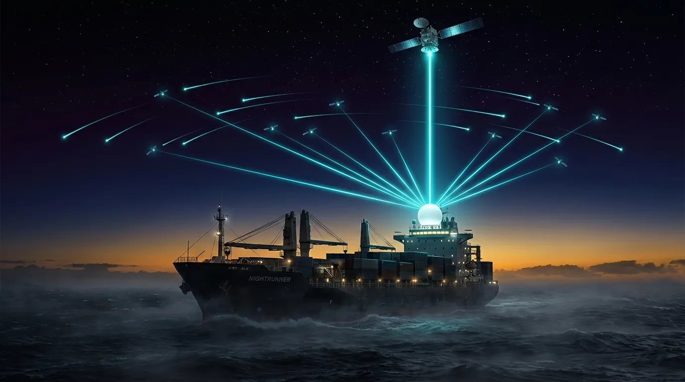
Maritime Satellite Internet: Ship Design and Acceptance
Plan maritime satellite internet for ships using route coverage, GMDSS boundaries, antenna placement, network segregation, contracts, and acceptance trials.
What changed: Rebuilt the guide around moving-vessel requirements, the GMDSS boundary, route-level authorization, model-specific terminal installation, onboard cyber segregation, contract evidence, and sea-trial acceptance; removed unsupported coverage, equipment, latency, handover, price, discount, sea-state, SLA, and vessel-type recommendations.
Maritime satellite internet is an end-to-end vessel system, not a terminal bolted to a deck. A workable design joins a route-authorized service, a compatible terminal and mount, safe RF and electrical integration, segregated onboard networks, shore-side operations, a support chain, and a contract that covers the required operating zones.
This guide is for moving commercial vessels and fleets. It explains how to specify and accept a service without assuming that “VSAT,” “LEO,” or a provider brand proves coverage, capacity, safety compliance, or reliability. Fixed islands and offshore platforms are covered separately in Maritime Solutions; the general service comparison remains in VSAT vs Starlink.
Scope note: Organization fact check updated 26 August 2026 against the primary references listed on this page. This is not a named expert approval, flag-state interpretation, class approval, radio survey, GMDSS compliance determination, structural design, EMC study, installation manual, or provider recommendation. The shipowner must obtain the applicable flag, class, coastal-state, port, network-operator, equipment-vendor, and competent professional approvals.
Ship Terminal Architecture | Provider Roles and Shortlisting | End-to-End Architecture
Quick Design Rule
Define one purchasable and testable vessel service:
qualified maritime service = vessel and route dossier
                           + legal operating scope
                           + named network, plan, and traffic policy
                           + terminal, mount, cables, and power
                           + RF, EMC, structural, and environmental acceptance
                           + onboard segmentation and security
                           + monitoring, support, and spares
                           + route trial and failure tests
                           + SLA, price, change, and exit terms
Reject these shortcuts:
| Shortcut | Why it fails | Required evidence |
|---|---|---|
| “VSAT means GEO with CIR and an SLA” | VSAT is a terminal/network class; orbit and commercial commitments belong to the actual offer | Satellite path, access method, rate definitions, measurement boundary, and signed SLA |
| “Starlink is available everywhere at sea” | Availability, permitted operating mode, plan, hardware, data treatment, and legal terms are separate and changeable | Route-level availability and written confirmation for the selected plan, terminal, seller, and date |
| “Commercial broadband satisfies GMDSS” | SOLAS chapter IV specifies maritime radiocommunication carriage and performance obligations | Flag/class/radio-survey confirmation for recognized equipment and service |
| “Two antennas equal redundancy” | Terminals may share sky blockage, power, routing, DNS, security, plan, provider, or gateway failures | Failure-domain diagram and witnessed failover tests |
| “The highest mounting point is best” | Structural load, radar interaction, cable route, exhaust, maintenance access, and changing obstruction geometry also matter | Approved structural, RF, EMC, power, cable, and blockage studies |
| “Nameplate speed proves ship performance” | Route, plan, load, satellite path, obstruction, weather, traffic policy, handover, and terrestrial routing affect results | Timestamped end-to-end route measurements and application tests |
Keep GMDSS and Commercial Broadband Separate
The IMO radiocommunications summary states that passenger ships and cargo ships over 300 gross tonnage on international voyages must carry specified terrestrial and satellite radiocommunication equipment under the GMDSS, whose regulations are contained in SOLAS chapter IV.
Do not count a general internet terminal, IP voice application, messaging app, or managed broadband link toward a GMDSS carriage requirement merely because it can transport communications. The flag Administration, recognized organization or class where applicable, radio surveyor, equipment approvals, recognized service arrangements, and the current SOLAS/GMDSS instruments determine compliance for the vessel.
Maintain an explicit service boundary:
| Traffic or system group | Design treatment |
|---|---|
| Statutory distress and safety communications | Keep within the approved GMDSS design, survey, maintenance, power, and operational regime; do not substitute commercial broadband without formal approval |
| Bridge, navigation, machinery, cargo, and other operational technology | Inventory data flows and remote access; assess safety impact; isolate and control connectivity under the vessel's safety and cyber risk processes |
| Company operations and administration | Define applications, destinations, directionality, authentication, data sensitivity, outage impact, and recovery needs |
| Crew welfare and passenger internet | Separate from privileged and operational networks; apply capacity, content, identity, privacy, abuse, and support policies appropriate to the operator |
| Terminal and network management | Restrict administrative access, protect credentials, log changes, define vendor access, and retain an out-of-band recovery method where required |
The broadband design can support business and welfare functions and may carry approved operational data. It does not erase the statutory communications boundary.
Build the Vessel and Route Dossier First
The same service can be viable on one voyage and unsuitable on another. Give every bidder the same dated dossier:
- vessel identity, type, dimensions, flag, class status, trading pattern, and required activation date;
- intended routes as coordinates or route corridors, ports, anchorages, territorial or service zones, seasonal deviations, and expected operating modes;
- deck drawings, current antenna plan, changing cargo or crane envelopes, mast and funnel geometry, radar and radio locations, hazardous or restricted spaces, and maintenance access;
- roll, pitch, yaw, vibration, wind, temperature, water-ingress, corrosion, and structural design inputs approved for the vessel rather than copied from another ship;
- available power, protection, earthing or bonding design, UPS or emergency-power boundary, heat rejection, cable routes, deck penetrations, network racks, and spare capacity;
- current WAN, firewall, switching, Wi-Fi, OT/IT boundary, remote-access, monitoring, logging, identity, DNS, time, and shore-management architecture;
- traffic matrix by application and direction, busy-period demand, latency/loss sensitivity, security class, outage consequence, and required degraded mode;
- procurement term, ownership model, support ports, crew capability, spare strategy, dry-dock or port-call constraints, and decommissioning obligations.
Do not replace the route dossier with a country list. A moving vessel crosses service zones, plan rules, beam or satellite paths, jurisdictions, weather conditions, and support regions.
Route Evidence Matrix
| Route leg or operating zone | Provider evidence date | Permitted plan and mode | Terminal and software | Network/path evidence | Known constraints | Backup and degraded mode | Acceptance status |
|---|---|---|---|---|---|---|---|
| Port or anchorage | |||||||
| Coastal or national waters | |||||||
| Ocean passage | |||||||
| High-latitude or special route | |||||||
| Diversion and emergency ports |
The categories are prompts, not legal conclusions. Ask the provider and responsible authorities to identify the applicable zone and authorization; do not infer rights from distance offshore or a colored marketing map.
Compare Services at Plan and Contract Level
Orbit is an architecture input, not a service specification. A GEO service can be shared and best effort. An NGSO service can have plan-specific priority treatment or an uptime SLA. Either can fail a route, application, support, security, or contract requirement.
For each offer, record:
| Field | Evidence to capture |
|---|---|
| Seller and service chain | Contracting legal entity, authorized reseller, upstream network, installer, field-support partner, NOC, and escalation authority |
| Operating rights | Countries and waters, stationary/in-motion/ocean use, vessel and terminal eligibility, order date, restrictions, suspension rules, and customer obligations |
| Satellite path | Orbit, satellite or constellation, beams or service areas, gateways or points of presence where disclosed, terrestrial handoff, and number of satellite hops |
| Traffic treatment | Forward/return expected or committed rates, CIR/MIR definition, priority or precedence, fair-use and network-management policy, quotas, overage, shaping, and upgrade rules |
| Performance | Measurement endpoints, latency/loss/jitter distributions, session continuity, availability definition, capacity evidence, and application acceptance thresholds |
| Terminal | Exact model and revision, approved mount, supported plan and motion mode, RF characteristics, control/monitoring behavior, environmental limits, software, and warranty |
| Operations | Monitoring boundary, alarms, customer portal or logs, support hours, severity levels, response/restoration, field dispatch, spares, and route coverage |
| Contract | SLA scope, exclusions, maintenance, credits, price basis, plan or network changes, equipment ownership, relocation, suspension, termination, and data/configuration handover |
Current Starlink Evidence Boundary
Starlink currently publishes separate documents for service-plan scope, expected performance, network-management and data treatment, Priority-plan SLA eligibility and calculation, and availability. Treat them as one dated evidence set.
An availability indication does not prove that the chosen plan permits the vessel's mode and route. Priority data is not automatically CIR. Expected performance is not a guaranteed rate. A published SLA does not apply unless the selected plan, terminal, service location or mode, and order terms meet its eligibility conditions. Recheck every document at order and renewal.
Managed VSAT Evidence Boundary
A “maritime VSAT” quote must name the satellite network, route coverage, beam or capacity arrangement, terminal, access method, forward and return rates, CIR/MIR or contention definitions, handover behavior where applicable, gateway and terrestrial handoff, support chain, and contract. Do not infer those properties from “GEO,” “Ku-band,” a radome, or the provider's fleet map.
Select and Integrate the Terminal
Mechanically tracked reflector systems and electronically steered arrays can both be valid ship terminals. Neither antenna class proves better availability, simpler approval, lower lifecycle cost, or superior performance for every vessel.
ETSI EN 302 340 V2.1.1 covers a defined class of Ku-band earth stations on board vessels, including radio emissions, pointing-related behavior, control and monitoring, and conformance tests. It explicitly states that installation requirements are outside its scope. ETSI EN 303 978 V2.2.1 covers a defined class of Ka-band earth stations on mobile platforms, including maritime vessels. These European radio-equipment standards do not by themselves prove global authorization, structural fitness, class acceptance, service compatibility, or correct installation on a particular ship.
Request a model-specific compliance and integration pack:
- equipment identity, hardware/software revision, declarations, test reports, approvals, service compatibility, and operator acceptance;
- transmit and receive bands, polarization, EIRP or spectral-density controls, antenna pattern, minimum operating elevation or scan mask, pointing or tracking behavior, and cessation-of-emission safeguards;
- stabilization or motion envelope, vessel sensor inputs, heading reference, calibration, reacquisition, handover, obstruction handling, and alarm behavior;
- environmental categories and test evidence for temperature, water ingress, corrosion, vibration, shock, wind, UV, and any radome or exposed connector arrangement;
- structural mount loads and fasteners, foundation, fatigue, vessel modifications, cable support, sealing, bonding, lightning or surge protection, and professional sign-off;
- above-deck and below-deck dimensions, mass, power quality, consumption, inrush, protection, heat dissipation, ventilation, network interfaces, and maintenance clearance;
- safe isolation, RF shutdown, lockout, access control, inspection intervals, consumables, onboard spares, special tools, warranty, and field-service procedure.
The Starlink Flat High Performance installation guide, for example, requires a clear sky view, warns that obstructions cause interruptions, and gives model-specific moving-vessel mounting and structural cautions. It is evidence for that kit and mount—not a universal flat-panel installation standard or approval for every ship.
Perform Blockage, RF, EMC, and Structural Studies
Build a three-dimensional obstruction mask for each terminal. Include fixed and changing geometry:
- mast, funnel, bridge, railings, cranes, booms, derricks, deck machinery, containers, cargo, and temporary equipment;
- exhaust, heat, spray, icing, wash-down, walking areas, lifting zones, and maintenance access;
- radar scanners, GMDSS and other radio antennas, GNSS, compasses or heading sensors, and nearby transmitters or receivers;
- vessel headings, heel, trim, roll and pitch envelope, loading conditions, route look directions, and terminal field of view;
- a second terminal's actual view and separation if diversity is claimed.
“Mount it as high as possible” is not an engineering decision. The selected position must satisfy the approved structural design, vendor limits, RF safety controls, EMC analysis, cable and power design, maintenance plan, and the least-bad obstruction envelope for the intended routes.
Maintain an interference and compatibility register. It should cover in-band and out-of-band risks, radar and radio interaction, inter-terminal coordination, GNSS and heading inputs, conducted and radiated emissions, bonding and grounding, cable separation, and the responsible test or approval. The applicable flag, class, radio, equipment, and spectrum requirements depend on the vessel and jurisdiction; an ETSI conformity claim is not a substitute for that determination.
Design the Onboard Network and Cyber Boundary
The April 2025 IMO Guidelines on maritime cyber risk management identify risks from interconnected ship systems, third parties, supply chains, and absent network segregation. They frame controls around concurrent Identify, Protect, Detect, Respond, and Recover functions.
Translate that risk-based guidance into the connectivity design:
- inventory every ship and shore system, owner, interface, protocol, data flow, dependency, remote-access path, update method, and recovery requirement;
- separate OT and safety-relevant systems, company IT, crew/passenger access, guest devices, terminal management, and vendor access with approved firewalls and access policy;
- use individual and privileged credentials, multi-factor authentication where appropriate, controlled vendor accounts, session approval, time limits, and revocation;
- minimize exposed services, restrict management interfaces, protect DNS and time dependencies, retain security and configuration logs, and synchronize timestamps;
- define patch, firmware, certificate, key, vulnerability, backup, restore, and configuration-baseline ownership across ship, shore, provider, and equipment vendors;
- prepare an isolation and degraded-operation procedure that does not depend on the failed or compromised broadband path;
- test incident detection, containment, reporting, restoration, and evidence retention without disrupting safe vessel operation.
Do not route privileged bridge or OT access through the crew network. QoS can prioritize packets; it cannot make an insecure topology safe or turn best-effort capacity into a contractual guarantee.
Specify Capacity and Performance Correctly
Create a traffic matrix before comparing headline speeds. For every application, state:
- source, destination, direction, protocol, session behavior, and number of simultaneous users or devices;
- normal, busy-period, burst, update, backup, and recovery volumes;
- minimum useful rate, tolerated delay/loss/jitter, reconnect behavior, and offline/degraded mode;
- priority class, security zone, business owner, safety impact, and whether traffic can be scheduled, cached, compressed, or blocked;
- test transaction and objective pass/fail threshold.
Then map the traffic matrix to the offer's actual service terms. Keep these quantities separate:
- expected rate, maximum or burst rate, CIR, data priority or precedence, fair-use threshold, quota, and overage;
- satellite-link availability, terminal availability, provider-edge availability, end-to-end reachability, and application success;
- propagation delay, provider-network latency, full end-to-end RTT, jitter distribution, packet loss, and session interruption;
- advertised service area, route authorization, instantaneous availability, and acceptance-tested coverage.
Do not assign a universal GEO or LEO latency to the ship design. Lower orbit altitude can reduce propagation distance, but the complete path includes satellite hops, gateways, inter-satellite routing where used, terrestrial backhaul, service edge, security overlay, congestion, and the application endpoint. The satellite latency guide provides the calculation boundary.
Treat Hybrid Connectivity as a Failure-Domain Design
A vessel may combine satellite networks, cellular links, port Wi-Fi, or other authorized paths. The number of links is less important than what fails together.
| Failure case | Evidence required before calling the design resilient |
|---|---|
| One antenna is blocked | Alternate terminal retains a usable view on the tested heading, attitude, and loading condition |
| One satellite service or plan is unavailable | Alternate is authorized on the route, active, funded, and sized for the defined degraded traffic set |
| Terminal or cable fails | Failure is isolated; spare, repair, or alternate path restores the required functions within the accepted time |
| Common power or network rack fails | Independent protection or an accepted degraded design prevents both paths from disappearing together |
| Router, firewall, DNS, identity, or security overlay fails | Recovery and bypass policy is documented, secured, and tested without creating an uncontrolled connection |
| Provider NOC or terrestrial handoff fails | Operational ownership and alternate escalation/path are known; monitoring can distinguish the fault boundary |
| A zone or operating mode is not permitted | Routing policy blocks the affected service and moves only approved traffic to an authorized alternative |
Do not promise seamless failover or bandwidth aggregation without testing session behavior. Source-address changes, NAT, VPNs, SD-WAN tunnels, DNS, application timeouts, asymmetric paths, and security policy can interrupt traffic even when a backup link is healthy.
Write an Enforceable Maritime Service Contract
The SLA and operating schedule should match the route and failure impact. Do not default to a generic 99.5% or 99.9% target.
Capture at least:
- covered vessels, terminals, plans, routes, zones, operating modes, software, and service start/end dates;
- exact measurement points, source of record, sampling and aggregation, billing period, time basis, and customer access to raw evidence;
- availability, performance, CIR or precedence, support, response, restoration, field-dispatch, and spare obligations where offered;
- outage and degradation thresholds, route or beam transitions, planned maintenance, weather, blockage, vessel power/LAN, regulatory events, port restrictions, force majeure, and other exclusions;
- incident notification, escalation, claim window, service credit, liability cap, chronic-failure remedy, termination right, and dispute evidence;
- plan, price, hardware, satellite/network, seller, upstream-provider, territory, and policy changes during the term;
- installation, acceptance, warranty, title and risk, software support, cybersecurity responsibilities, data handling, return, removal, and configuration handover.
Compare total cost over one common scenario:
TCO = survey and engineering
    + approvals and vessel modifications
    + terminal, mount, cables, power, and network equipment
    + installation, port time, travel, commissioning, and acceptance
    + recurring service, data, licences, support, and management
    + spares, maintenance, logistics, repairs, and software lifecycle
    + changes, overage, suspension, relocation, and price escalation
    + decommissioning, restoration, exit, and residual obligations
Do not publish or rely on generic terminal prices, monthly budgets, installation ranges, or fleet discount percentages. Quotes vary by vessel, route, plan, hardware, approvals, term, service boundary, currency, tax, logistics, and date.
Run Dockside and Sea Acceptance Tests
Agree the test plan, instruments, safety controls, data ownership, witnesses, thresholds, and remedies before installation. Do not create hazardous weather, maneuvering, or RF conditions merely to test connectivity.
Phase 1: Document and Installation Acceptance
- verify model, revision, approvals, certificates, drawings, mount and fastener records, cable and penetration inspection, sealing, power/protection, bonding, labels, software, configuration, licences, and inventory;
- approve structural, obstruction, RF safety, EMC, network, cyber, and operational records;
- confirm monitoring, alarms, logs, support contacts, spares, manuals, training, isolation, and recovery procedures.
Phase 2: Controlled Dockside Tests
- prove terminal acquisition, correct network/plan, addressing, DNS, routing, VPN or SD-WAN, segmentation, QoS policy, monitoring, timestamping, log export, and management access;
- measure both directions between named endpoints and run the defined application transactions;
- remove each permitted dependency in turn to prove alarm, failover, degraded capacity, recovery, and return-to-primary behavior.
Phase 3: Route-Representative Sea Trial
- collect synchronized position, heading, vessel motion, route leg, terminal state, obstruction events, signal and network metrics, policy changes, and application outcomes;
- cover approved headings, turns, speeds, loading or deck configurations, known obstruction sectors, network or beam transitions, and representative operating zones that can be tested safely;
- test busy-period traffic, session continuity, permitted failovers, support ticket handling, shore escalation, and recovery;
- record untested route segments and environmental limits as open conditions rather than declaring global acceptance.
Phase 4: Acceptance Record
Retain raw data, configuration exports, versions, diagrams, photographs, test scripts, timestamps, incidents, exceptions, corrective actions, retests, witness signatures, and the exact accepted service and hardware baseline. Tie failed thresholds to remediation, commercial relief, or rejection.
Award Gates
Do not award until every mandatory gate has an accountable approver and evidence:
- GMDSS and statutory communications boundary accepted by the responsible maritime compliance parties.
- Route, zone, plan, motion mode, terminal, and authorization evidence accepted for the intended operation.
- Structural, RF, EMC, electrical, environmental, and installation design accepted for the vessel.
- Traffic matrix, degraded mode, security segmentation, monitoring, and recovery accepted by ship and shore owners.
- SLA, support, spares, change control, TCO, and exit terms accepted commercially.
- Dockside, route trial, failure, support, and application tests passed or exceptions formally accepted.
A vessel type alone should never select the architecture. Two cargo ships can have different routes, deck geometry, cargo obstructions, applications, risk tolerance, approvals, crew support, and contract options.
FAQ
What is the best maritime satellite internet for ships?
There is no universal best service. Compare purchasable offers for the exact vessel, route, plan, terminal, operating mode, installation, application set, support chain, and contract date. Reject any option that fails a statutory, authorization, installation, security, degraded-operation, or acceptance gate.
Can Starlink replace maritime VSAT?
It can be a candidate primary or secondary commercial link when the selected service, plan, hardware, route, installation, performance, operations, and contract pass the requirements. It is not a blanket substitute for every VSAT service and should not be treated as evidence of GMDSS compliance. Recheck current Starlink plan, availability, fair-use, SLA, and installation documents for the order.
Does LEO eliminate maritime latency problems?
Lower altitude reduces the satellite propagation component, but it does not eliminate gateway, terrestrial, processing, routing, congestion, handover, security-overlay, or application delays. Test distributions and session outcomes end to end on the route; do not award on one advertised RTT.
Which service works on polar or remote-ocean routes?
No orbit label proves route coverage. Obtain dated route-level availability, permitted-use, terminal, capacity, support, and regulatory evidence for every candidate, then perform representative trials. Record untested segments and seasonal or service-change risk.
What availability SLA should a ship request?
Derive it from the vessel's outage consequence, degraded mode, repair opportunities, route, and failure model. The contract must define what is measured, where, over what period, with which exclusions and remedy. A percentage without those fields is not an engineering requirement.
Does a ship need two satellite terminals?
Only the blockage, failure, traffic, and risk analysis can answer that. Two terminals help only when their views, mounts, power, cables, network paths, services, authorization, and support remove the required failure cases. Test the claimed independence.
How much does maritime satellite internet cost?
Use same-scope supplier quotes and the TCO formula above. Generic hardware and monthly-price ranges omit vessel modifications, approvals, installation, port time, route rights, data treatment, support, spares, lifecycle changes, tax, and exit costs.
Does commercial satellite broadband satisfy GMDSS requirements?
Not by itself. GMDSS obligations arise from SOLAS chapter IV and the applicable flag-state, equipment, service, survey, maintenance, and operating requirements. Obtain a vessel-specific determination from the responsible maritime authorities and professionals.
Related Guides
- VSAT vs Starlink — general plan- and contract-level service comparison
- Satellite Service Providers — operator, reseller, integrator, and support roles
- Ship and Satellite Terminal Architecture — antenna, RF chain, interfaces, and acceptance boundaries
- End-to-End Architecture — service path, owners, demarcations, and measurement points
- Satellite Latency Comparison — propagation and end-to-end latency calculation boundaries
- QoS over Satellite — traffic classification, shaping, and application behavior
- Maritime Solutions — fixed islands, archipelagos, and offshore platforms
Author

Organizational byline for SATCOM Index technical content. A named technical reviewer appears separately only when identity, scope, and permission are verified.
Categories
More Posts
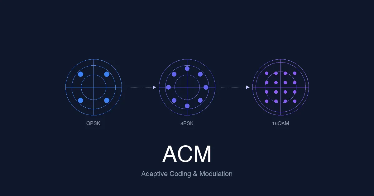
Adaptive Coding and Modulation (ACM) Explained: How Satellite Networks Maintain Link Quality
Engineering guide to adaptive coding and modulation in satellite systems covering signal quality measurement, MODCOD selection algorithms, DVB-S2/S2X ACM capabilities, rain fade response, and ACM design for HTS and LEO networks.
SCADA over Satellite: How Industrial Monitoring and Control Work in Remote Networks
Engineering guide to SCADA over satellite covering industrial telemetry, latency, QoS design, GEO vs LEO trade-offs, and deployment best practices.
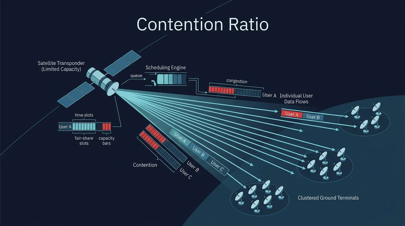
Satellite Contention Ratio Explained: What Shared Capacity Really Means for Performance
Engineering guide to satellite contention ratio covering shared vs dedicated bandwidth, busy-hour behavior, CIR vs contention, use-case trade-offs, and how to evaluate provider offers.