
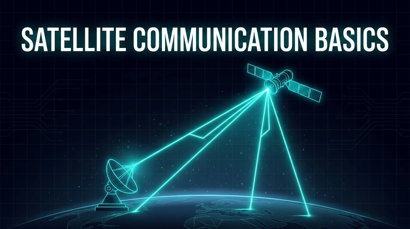
Satellite Communication Basics: How Satcom Works
Learn satellite communication basics through one end-to-end signal path: uplink, payload, downlink, orbits, frequency labels, link budget, and latency.
What changed: Removed unstable provider, constellation, speed, equipment-size, and generic band claims; corrected orbit boundaries, GEO latency, uplink/downlink, and frequency-allocation statements; and rebuilt the guide around a reproducible end-to-end signal path with current ITU and ESA sources.
Satellite communication, or satcom, transfers information over a radio path that includes at least one space station. The satellite can relay, switch, or regenerate the signal, but the end-to-end service still depends on earth stations, antennas, spectrum, gateways, control systems, and terrestrial networks.
That definition corrects a common misconception: satellite service can reduce dependence on local cable or cellular infrastructure at the user site, but it is not independent of ground infrastructure. A gateway, control path, application endpoint, power source, and licensed radio resources still exist somewhere in the system.
This guide follows one signal from source to destination, then shows how orbit, frequency, antennas, propagation, and network design change the result.
End-to-End Architecture | VSAT Architecture | Link Budget Guide
The End-to-End Signal Path
A simplified transparent satellite path is:
source data | router or application interface | modem: framing, coding, and modulation | transmitter and antenna | Earth-to-space radio link | satellite receive antenna and payload | space-to-Earth radio link | receive antenna and receiver | demodulation, decoding, and routing | destination service or user
The radio portion is only part of the service. Queueing, terrestrial backhaul, DNS, security processing, application servers, and congestion can affect performance after the signal leaves the satellite path.
Step 1: Convert information into a radio signal
Voice, video, telemetry, or IP packets are framed and encoded. A modem applies forward-error correction and maps the coded bits to modulation symbols. The RF chain converts the signal to the assigned transmit frequency, amplifies it, and feeds the antenna.
The transmitter must operate within the equipment rating, satellite-operator access plan, coordination conditions, and national authorization. A frequency-band label or amplifier name is not permission to transmit.
Step 2: Send the uplink
The uplink is the Earth-to-space direction. The transmitting earth station contributes carrier power, antenna gain, pointing, polarization, and equipment losses. The path adds free-space loss and propagation effects.
The word uplink identifies direction, not one universal frequency. Exact allocations depend on radiocommunication service, ITU Region, direction, footnotes, coordination, and national implementation under the ITU Radio Regulations Article 5.
Step 3: Process the signal in the payload
A satellite payload can be:
- Transparent: it filters, amplifies, switches, or frequency-translates the radio signal without terminating the complete user protocol.
- Regenerative: it demodulates and regenerates the signal onboard and may switch or route traffic before retransmission.
Not every payload performs the same frequency conversion, beam switching, or onboard routing. These are architecture choices, not universal properties of satellite communication.
Step 4: Send the downlink
The downlink is the space-to-Earth direction. The satellite transmit power and antenna pattern establish EIRP in the receiving site's direction. Free-space and atmospheric losses reduce the signal before the receiving antenna and receiver contribute gain and noise performance.
Paired satellite systems often use different Earth-to-space and space-to-Earth frequencies so transmit and receive paths can be separated, but “the uplink is always higher than the downlink” is not a general rule. The actual frequency plan must be read from the applicable allocation and network assignment.
Step 5: Recover and route the information
The receiver downconverts, filters, demodulates, and decodes the signal. The recovered traffic then enters a local device, a gateway, a private network, the internet, or another satellite path.
A successful RF demodulation does not guarantee good application performance. The terrestrial and application sections must be measured as part of the same end-to-end path.
Core Terms Without the Ambiguity
| Term | Practical meaning |
|---|---|
| Earth station | Radio station located on Earth or in the main part of Earth's atmosphere that communicates with space stations or other earth stations through space objects |
| Space station | Radio station located on an object beyond, intended to go beyond, or having been beyond the main part of Earth's atmosphere |
| Uplink | Earth-to-space transmission direction |
| Downlink | Space-to-Earth transmission direction |
| Satellite hop | One ground-station-to-satellite-to-ground-station route |
| User link | Radio path between a user terminal and satellite |
| Feeder link | Radio path connecting a satellite system to a gateway or other earth station that feeds the service |
| Beam | Directional antenna coverage region; it is not automatically a separate network or carrier |
| Gateway | Earth station and associated baseband/terrestrial functions that connect the satellite path to another network |
These roles can be combined physically. For example, a compact hub may include gateway RF, modem banks, control, management, routing, and security. Keeping the logical roles separate makes failures and performance easier to diagnose.
Frequency Bands: Labels Are Not Allocations
Terms such as L, C, Ku, and Ka are useful shorthand, but they do not identify a legal operating frequency by themselves. ITU-R V.431-9 warns that letter symbols should be accompanied by corresponding frequency limits or at least a frequency when first used.
Its Table 4 gives the following examples for space radiocommunications:
| Letter label | Nominal space-radiocommunication designation | Example frequency ranges in V.431-9 |
|---|---|---|
| L | 1.5 GHz band | 1.525–1.710 GHz |
| S | 2.5 GHz band | 2.500–2.690 GHz |
| C | 4/6 GHz band | 3.4–4.2, 4.5–4.8, and 5.85–7.075 GHz |
| Ku | 11/14 or 12/14 GHz bands | 10.7–13.25 and 14.0–14.5 GHz |
| K | 20 GHz band | 17.7–20.2 GHz |
| Ka | 30 GHz band | 27.5–30.0 GHz |
| V | 40 GHz band | 37.5–42.5 and 47.2–50.2 GHz |
These are nomenclature examples, not a complete worldwide allocation table. The ITU Radio Regulations Article 5 divides allocations by frequency, radiocommunication service, direction, and ITU Region, with footnotes and coordination conditions. National administrations then authorize actual assignments.
What frequency changes
Frequency influences several linked design terms:
- Antenna behavior: for the same physical aperture and efficiency, gain and beamwidth change with wavelength.
- Free-space calculation: ITU-R P.525-5 expresses free-space basic transmission loss using distance and wavelength or frequency.
- Propagation: gases, precipitation, clouds, scintillation, and other effects depend on frequency, elevation, climate, and time percentage; ITU-R P.618-14 supplies Earth-space prediction methods and validity ranges.
- Hardware: amplifier efficiency, receiver noise, feed loss, surface accuracy, pointing, and radome performance vary by design.
- Spectrum rights: available bandwidth, service direction, sharing, and power limits depend on the applicable regulatory and operator plan.
Lower frequency does not automatically mean “better,” and higher frequency does not automatically mean “more throughput.” Throughput also depends on authorized bandwidth, spectral efficiency, link quality, resource allocation, and network load.
For a band-focused treatment, see Satellite Frequency Bands Explained.
Orbits: Classification Is Not Performance
Orbit affects range, motion, visibility, handover, tracking, and coverage geometry. It does not by itself specify a measured latency or throughput.
ESA's Space Environment Report 2026, Table 1.2 uses these catalogue boundaries:
- LEO: perigee and apogee from 0 to 2,000 km.
- MEO: perigee and apogee from 2,000 to 31,570 km.
- Crossing, navigation, transfer, geosynchronous, and other classes are tracked separately.
A geostationary satellite is more specific than “a satellite near GEO altitude.” ITU Radio Regulations No. 1.189 defines it as a geosynchronous satellite in a circular, direct, equatorial orbit that remains fixed relative to Earth, with the definition extended to approximately fixed cases. The nominal altitude is about 35,786 km.
Orbit tradeoffs to record
| Architecture question | Lower-orbit systems | Geostationary systems |
|---|---|---|
| Apparent motion | Satellites move relative to a fixed site | Satellite appears approximately fixed |
| Terminal behavior | Tracking, acquisition, and handover may be required | A fixed site can normally maintain one pointing direction |
| Range | Changes with satellite position and elevation | Large but comparatively stable for a fixed site pair |
| Coverage continuity | Depends on constellation, gateway, and handover design | Depends on beam footprint and look angle |
| End-to-end route | May include changing gateways, satellites, or inter-satellite links | Often one satellite hop, but multi-hop paths also exist |
These are architecture tendencies, not service promises. Payload processing, gateway placement, beam connectivity, terrestrial routing, and resource scheduling can outweigh the orbit label.
A Reproducible Propagation Lower Bound
The exact SI speed of light is 299,792.458 km/s; see the BIPM SI Brochure, Section 2.2.
For an intentionally simplified transparent satellite hop, assume zero ground separation, an overhead satellite at altitude h, the same path in both directions, and no processing, scheduling, queueing, or terrestrial delay:
one-way ground-satellite-ground distance = 2h one-way propagation time = 2h / c propagation-only RTT = 4h / c
Using example altitudes, not service measurements:
| Example altitude | Idealized one-way hop distance | Propagation-only RTT lower bound |
|---|---|---|
| 550 km | 1,100 km | 7.34 ms |
| 8,000 km | 16,000 km | 106.74 ms |
| 35,786 km | 71,572 km | 477.48 ms |
The zero-ground-separation assumption makes these physical lower bounds rather than deployable route models. Real user and gateway sites have different slant ranges and are not both directly below the satellite.
RFC 2488 Section 2 reports 239.6 ms one way for an ideal GEO ground-satellite-ground hop and 279.0 ms near the edge of view. The corresponding propagation-only RTT is 479.2–558.0 ms before serialization, scheduling, modem processing, queueing, terrestrial routing, or application delay.
For a full comparison of propagation floors and measured service RTT, see Satellite Latency: GEO vs MEO vs LEO.
Link Budget: The Signal Ledger
A link budget accounts for gains and losses between declared reference planes. A simplified received-carrier calculation is:
received carrier power = transmit power
- transmit-side losses
- transmit antenna gain
- propagation and path losses
- receive antenna gain
- receive-side losses
The complete performance calculation also needs:
- EIRP: actual carrier power combined with antenna gain in the transmit direction.
- Free-space loss: calculated from distance and frequency under the P.525 free-space model.
- Atmospheric and propagation loss: gases, rain, clouds, scintillation, polarization, and other applicable terms.
- Receive G/T: receive antenna gain relative to system noise temperature.
- Noise bandwidth: noise increases with the bandwidth used for the receiver calculation.
- Carrier allocation: total payload or transponder power cannot be assigned to one carrier without an allocation basis.
- Waveform: modulation, coding, pilots, framing, roll-off, and implementation loss determine the required signal quality and net data rate.
- Interference: co-channel, adjacent-system, cross-polar, intermodulation, and terrestrial interference may limit the link before thermal noise does.
Every term needs a unit, direction, frequency, reference plane, and operating condition. A positive clear-sky margin alone does not establish an annual availability target.
Calculate a Satellite Link Budget | Calculate EIRP | C/N, C/N0, and Eb/N0
Worked Path: Remote User to Gateway Service
Consider a hypothetical user terminal connected to an application through a transparent GEO satellite and one ground gateway.
Request direction
- The user's device sends a packet to the terminal router and modem.
- The modem frames, codes, and modulates the packet according to its assigned return resource.
- The terminal transmits Earth-to-space.
- The transparent payload relays the signal toward the gateway beam.
- The gateway receives, demodulates, decodes, and routes the packet over the terrestrial network.
- The application processes the request.
The terminal-to-gateway radio path is one satellite hop: ground to satellite to ground.
Response direction
- The application sends the response toward the gateway service edge.
- The forward-link system schedules, frames, codes, and modulates the response.
- The gateway transmits Earth-to-space.
- The payload relays the signal toward the user beam.
- The terminal receives and decodes it, then delivers it to the user device.
The response is another one-way satellite hop. A request-response measurement therefore includes four radio legs, plus every processing and terrestrial term in both directions.
If the destination is another remote terminal and the network routes through the same ground gateway, the packet can traverse two satellite hops in one direction. A supported direct mesh or regenerative path can change that hop count. See Satellite Network Topology.
What Determines Real Service Performance?
Latency
Latency is the sum of propagation, serialization, framing, access scheduling, payload and modem processing, queueing, terrestrial routing, security processing, and application response. Orbit altitude establishes only part of the propagation term.
Throughput
Net application throughput is not raw RF bandwidth. It depends on symbol rate, roll-off, modulation and coding, frame overhead, retransmission, protocol overhead, resource sharing, congestion, and the slowest section of the end-to-end path.
Availability
Availability needs a time percentage, service area, link direction, propagation model, equipment reliability, maintenance assumptions, power and backhaul design, restoration process, and defined failure boundary. “C-band is reliable” or “Ka-band needs a fixed fade margin” is not an availability calculation.
Coverage
A footprint or beam contour describes radio coverage under stated assumptions. Service also requires gateway visibility, user authorization, capacity, compatible equipment, pointing or tracking, and an operational terrestrial path.
Capacity
Payload bandwidth and power, beam reuse, gateway resources, scheduling, traffic demand, contention, and QoS determine usable capacity. A satellite's aggregate design throughput is not an individual user's guaranteed rate.
Common Application Patterns
| Application pattern | Traffic characteristic | Architecture question |
|---|---|---|
| Broadcast or content distribution | Predominantly one-to-many | Is a return path required, and how is receiver authorization handled? |
| Enterprise access or backhaul | Bidirectional, often bursty | Where is the gateway, and how are capacity and QoS shared? |
| Maritime, aeronautical, or land mobility | Moving terminal and changing geometry | How are tracking, blockage, beam changes, and regulatory areas handled? |
| Telemetry and control | Often small messages with availability or timing constraints | Is access deterministic, contention-based, or store-and-forward? |
| Emergency or temporary connectivity | Rapid deployment and changing conditions | What power, pointing, spectrum authorization, and restoration plan are available? |
| Remote media contribution | Sustained high-rate or time-critical uplink | Can the assigned uplink, terminal EIRP, gateway, and terrestrial handoff sustain the requirement? |
These categories do not prescribe an orbit, band, terminal, or provider. The traffic matrix and operational constraints should drive the selection.
Beginner's Engineering Checklist
Before comparing satellite services or equipment, write down:
- Endpoints: where the user, gateway, and application actually are.
- Traffic matrix: direction, peak and sustained rate, burstiness, packet size, and traffic classes.
- Path: orbit, satellite hops, beams, gateways, payload processing, and terrestrial routing.
- Frequency assignment: exact transmit and receive frequencies, service, ITU Region, licence, and operator plan.
- Terminal reference planes: transmit power, losses, antenna gain, receive G/T, pointing, and tracking.
- Propagation objective: site coordinates, elevation, polarization, climate data, and time percentage.
- Waveform and access: symbol rate, roll-off, modulation, coding, scheduling, contention, and overhead.
- Performance target: latency percentile, net throughput, loss, jitter, availability, and measurement endpoint.
- Resilience: gateway, backhaul, power, payload, control-plane, and equipment failure domains.
- Acceptance evidence: calibrated measurements, test load, timestamp, weather, software version, and responsible operator.
This converts a vague request for “satellite internet” into inputs that can be engineered and tested.
Common Beginner Mistakes
- Saying satellite is independent of ground infrastructure. The user site may avoid local cable, but gateways, controls, power, and terrestrial networks remain.
- Treating a band label as a frequency assignment. State actual transmit and receive ranges and the applicable service and Region.
- Assuming uplink frequency is always higher. Direction and allocation must be verified for the specific network.
- Assigning one RTT to an orbit. Count the radio path and add processing, scheduling, terrestrial, and application terms.
- Calling every payload a frequency-translating analogue repeater. Transparent, digitally processed, and regenerative payloads behave differently.
- Inferring throughput from orbit or band. Capacity allocation, link quality, waveform, overhead, load, and terrestrial bottlenecks matter.
- Using a universal dish or amplifier range. Equipment follows the link budget, access plan, environment, and authorization.
- Comparing total satellite capacity with one user rate. Aggregate design capability and committed service performance are different quantities.
Frequently Asked Questions
How does satellite communication work?
An earth station encodes and transmits information on an Earth-to-space radio link. A satellite payload relays, switches, or regenerates the signal and transmits it on a space-to-Earth link. A receiving earth station decodes the information and passes it to the destination network or user.
What is the difference between satellite communication and satellite internet?
Satellite communication is the broader radio and network discipline. Satellite internet is one service built on it. Other services include broadcast distribution, private networks, mobility, telemetry, media contribution, and emergency communications.
Which satellite frequency band is best?
There is no universal best band. Use the authorized frequency plan and compare antenna performance, propagation, available bandwidth, interference, equipment, coverage, and service requirements for the actual sites.
Is GEO too slow for interactive applications?
GEO imposes a large propagation floor, but suitability depends on the application's latency tolerance, route, queueing, transport behavior, and service design. Avoid replacing an application assessment with a blanket “suitable” or “unsuitable” label.
Does rain reduce satellite EIRP?
Atmospheric rain attenuates the propagation path after transmission; it does not redefine the EIRP leaving the antenna. Wet feed or radome effects can change terminal performance before radiation and should be accounted for separately.
Does a higher-frequency band always provide more throughput?
No. Higher frequencies may make more spectrum or smaller apertures practical in a particular system, but authorized bandwidth, link quality, propagation, antenna performance, coding, power, sharing, and network load determine usable throughput.
Key Takeaways
- Satcom is an end-to-end system, not only a satellite in orbit.
- Uplink and downlink describe direction; exact frequencies come from an allocation and assignment.
- Letter bands are shorthand and must be paired with actual frequency limits.
- Orbit changes geometry and propagation but does not define measured service latency or throughput.
- Link budgets require explicit reference planes, gains, losses, noise, interference, bandwidth, and operating conditions.
- Product speeds, constellation counts, equipment sizes, and generic availability figures do not belong in a timeless fundamentals guide without current primary evidence and a clear scope.
Related Articles
- End-to-End Satellite Architecture — Map user, terminal, payload, gateway, and terrestrial paths
- VSAT Network Architecture — Separate terminal, gateway, NCC, NMC, payload, and service-edge roles
- Satellite Frequency Bands — Examine frequency labels, allocations, propagation, and equipment tradeoffs
- Satellite Latency Comparison — Calculate propagation floors and separate them from service RTT
- Satellite Link Budget Calculation — Build a reproducible gain, loss, noise, and margin ledger
- Satellite EIRP Explained — Define directional radiated power and reference planes
- Satellite Network Topology — Compare star, mesh, and hybrid traffic paths
Author

Organizational byline for SATCOM Index technical content. A named technical reviewer appears separately only when identity, scope, and permission are verified.
Categories
More Posts

Terminals & Remotes
User terminal equipment, remote site configurations, and installation guidelines.

Satellite Glossary: M-R
Satellite communication terminology and definitions from M to R.
Satellite Carrier Spacing Explained: Why Guard Bands Matter in RF Planning
Engineering guide to satellite carrier spacing covering guard bands, RF planning trade-offs, spectral efficiency, and adjacent carrier interference.