
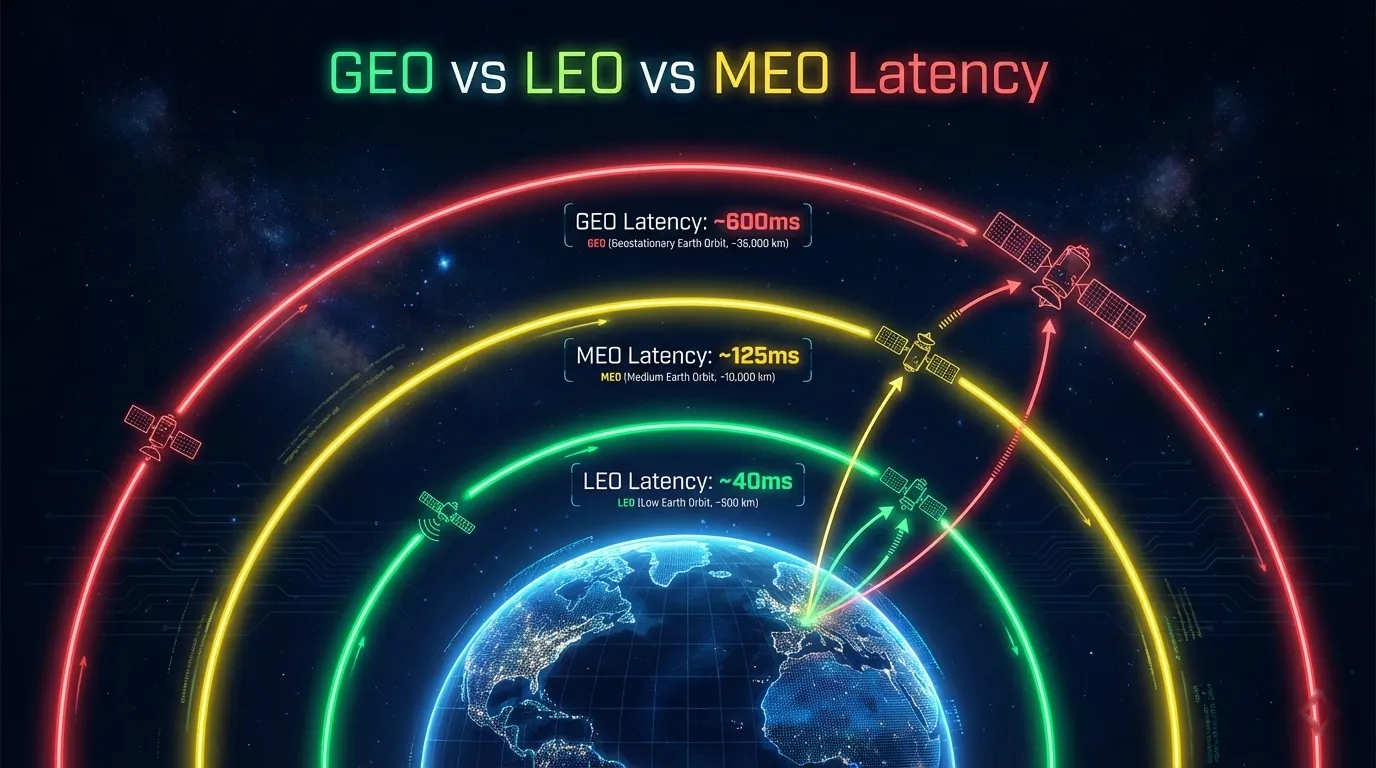
Satellite Latency: GEO vs MEO vs LEO
Calculate satellite latency from path length, then compare GEO, MEO, and LEO propagation floors with service RTT, application limits, and test results.
What changed: Corrected the GEO path-length definitions and ESA orbital-class boundary, separated propagation floors from measured service RTT, added reproducible calculations and boundary conditions, and replaced generic claims with document-level primary sources.
Satellite latency is not a single number assigned to an orbit. It is the sum of propagation, transmission, scheduling, processing, queueing, and terrestrial-routing delays along a specific path. Orbit altitude sets a physical floor, but gateway placement, elevation angle, inter-satellite routing, congestion, and the application endpoint determine the result a user measures.
For one transparent GEO satellite hop, the radio path from one earth station through the satellite to another earth station takes about 240–280 ms one way. A request and its reply therefore require roughly 480–560 ms of satellite propagation alone, before other network delays are added. These figures follow the path definitions in IETF RFC 2488, Section 2, which reports 239.6 ms for ideal geometry and 279.0 ms near the edge of coverage.
Lower orbits shorten the space path, but a fair comparison must separate a calculated propagation floor from operational service latency. This guide shows both and makes every calculation reproducible.
Glossary: GEO, LEO, Latency | End-to-End Architecture
Define the Path Before Calculating Latency
Three terms are often mixed together:
- Space leg: one earth-to-satellite or satellite-to-earth segment.
- Satellite hop: an earth-station-to-satellite-to-earth-station path containing two space legs.
- Round-trip time (RTT): the time for traffic to reach the destination and for a response to return. A symmetric single-satellite path contains four space legs in one RTT.
This distinction fixes a common GEO error. Dividing 35,786 km by the speed of light gives about 119 ms. That is only one vertical ground-to-satellite leg. It is not the one-way delay between a user terminal and a gateway, and it is not RTT.
The propagation calculation is:
t = d / c

t     propagation time, seconds
d     total signal-path distance, kilometres
c     299,792.458 kilometres per second in vacuum
The value of c is exact in SI units; see the BIPM SI Brochure, Section 2.2. For a transparent satellite path with user slant range r_user and gateway slant range r_gateway:
one-way space delay = (r_user + r_gateway) / c
space-only RTT      = 2 × (r_user + r_gateway) / c
Use slant range, not altitude, when site coordinates and satellite longitude or ephemeris are available. Altitude equals slant range only in the simplified overhead case. For a fixed GEO satellite, the GEO look-angle calculator can check azimuth, elevation, and idealized horizon visibility. It does not calculate slant range or operational service latency.
Worked Propagation Example
The following calculation intentionally uses a simplified boundary condition: the satellite is directly above both ends of an idealized short ground path, the same satellite carries both directions, and processing, queueing, terrestrial backhaul, retransmission, and inter-satellite links are zero. It is a lower-bound comparison, not a service promise.
| Example orbit altitude | One-way path distance (2h) | One-way space delay | Space-only RTT (4h/c) |
|---|---|---|---|
| LEO, 550 km | 1,100 km | 3.7 ms | 7.3 ms |
| MEO, 8,000 km | 16,000 km | 53.4 ms | 106.7 ms |
| GEO, 35,786 km | 71,572 km | 238.7 ms | 477.5 ms |
Example for GEO:
one-way space delay = 71,572 km / 299,792.458 km/s
                    = 0.23874 s
                    = 238.7 ms

space-only RTT      = 2 × 238.7 ms
                    = 477.5 ms
The result is close to RFC 2488's 239.6 ms ideal one-way value. Real GEO sites are not both directly below the spacecraft. Longer slant ranges explain why the same RFC gives up to 279.0 ms for one satellite hop at the edge of view and notes that an RTT may reach at least 558 ms before other delays.
Boundary Conditions That Change the Result
The simple 4h/c model is useful for checking units and order of magnitude, but it does not model a deployed network. Replace it with full path distance when any of these conditions applies:
- the user or gateway operates at a low elevation angle, increasing slant range;
- traffic crosses one or more inter-satellite links;
- a star network sends remote-to-remote traffic through two satellite hops;
- the return route differs from the forward route;
- a distant gateway adds a long terrestrial backhaul segment;
- demand-assigned access makes a terminal wait for a transmit slot;
- congestion, retransmission, encryption, or application processing is material.
GEO Satellite Latency
A geostationary spacecraft has a nominal altitude of about 35,786 km above the equator. It appears fixed to a ground observer, allowing fixed-pointing antennas and persistent wide-area coverage.
For a single transparent GEO hop, use 240–280 ms one way as a documented space-propagation range, not 120–140 ms. The corresponding propagation RTT is approximately 480–560 ms. RFC 3135, Section 5.1.1 independently describes 240–280 ms sender-to-receiver propagation in geosynchronous VSAT networks and notes that queueing and shared-channel access can add much more.
Measured IP RTT may be higher because the ping target is beyond the satellite gateway, queues form under load, or the access protocol waits for capacity. A transparent bent-pipe transponder does not justify adding a generic 5–15 ms processing allowance; equipment and waveform delay must be taken from the actual modem, codec, scheduler, and payload specifications.
GEO delay is noticeable in conversation, remote desktops, multi-round-trip authentication, and short transactional requests. It does not make every interactive application unusable. Voice can operate over GEO when echo control, jitter management, packet loss, and user expectations are handled, while bulk transfer, broadcast, telemetry, and asynchronous workflows are often less sensitive.
MEO Satellite Latency
MEO covers a broad altitude range between LEO and the higher orbital regimes. The exact boundary depends on the classification system. This page follows the ESA Space Environment Report 2026, Table 1.2: its LEO class has both perigee and apogee from 0 to 2,000 km, while its MEO class has both from 2,000 to 31,570 km. The report classifies boundary-crossing orbits separately. A service's actual orbit must therefore be used instead of a generic “MEO altitude.”
At an illustrative 8,000 km altitude, the idealized space-only RTT is 106.7 ms. Slant range and network overhead move the operational result above that floor. SES currently describes O3b mPOWER as providing 150 ms satellite latency across large regions in its official system overview. That operator figure is a service reference, not a universal value for every MEO constellation.
MEO can support interactive cloud access, voice, and video with substantially less delay than GEO, while using fewer satellites per coverage area than a lower LEO constellation. Terminals still need tracking and handover arrangements because MEO spacecraft are not fixed in the sky.
LEO Satellite Latency
LEO extends up to 2,000 km under the ESA classification used here. A 550 km overhead example produces only 7.3 ms of space-only RTT, but that figure omits the moving slant geometry, gateway path, routing, processing, queueing, and any inter-satellite links.
Operational service figures are therefore more useful for application planning. Starlink's official specifications state 25–60 ms latency on land and more than 100 ms in some remote locations. These numbers illustrate why “LEO latency” is not a single constant: gateway availability and route geography can outweigh the few milliseconds in the ideal altitude-only calculation.
LEO delay also varies over time. The serving satellite changes, slant range changes during a pass, and the chosen ground or inter-satellite route may change. For engineering acceptance, record latency distribution and handover behavior, not only a best-case ping.
Satellite Beam Handover Explained | Hybrid Satellite Networks
Modeled Floors vs Operational References
| Orbit example | Space-only RTT floor | Documented operational reference | What the comparison means |
|---|---|---|---|
| LEO at 550 km | 7.3 ms | Starlink: 25–60 ms on land; 100+ ms in some remote areas | Routing and service architecture dominate above the altitude-only floor |
| MEO at 8,000 km | 106.7 ms | SES O3b mPOWER: 150 ms satellite latency | The operator value includes more than vertical vacuum propagation |
| GEO at 35,786 km | 477.5 ms | RFC 2488: about 479–558 ms propagation RTT across ideal-to-edge geometry | Internet, scheduling, and queueing delay are additional |
Do not compare the middle column for one system with the service column for another. One is a model with declared assumptions; the other is an observed or marketed network-level reference.
Application Impact
Voice and Video
ITU-T G.114, Section 4 does not define 150 ms as a universal pass/fail limit. It says that most applications experience essentially transparent interactivity below 150 ms one way, while highly interactive tasks can be affected at lower values. For general network planning, it recommends not exceeding 400 ms one way and recognizes exceptional cases such as an unavoidable double satellite hop.
Voice quality also depends on codec delay, jitter buffer, packet loss, echo control, and the two parties' conversational behavior. Use the ITU-T E-model when planning speech quality rather than judging a service from propagation delay alone.
Web, Authentication, and Remote Desktop
Interactive workflows often require several dependent request-response exchanges. High RTT makes each serial exchange visible even when bandwidth is ample. DNS caching, connection reuse, modern transports, edge caching, and local breakout can reduce the number or distance of these exchanges, but they cannot remove the orbital propagation floor.
Remote desktop and command-line sessions expose delay immediately because user input waits for visual or textual feedback. Test the actual application against representative endpoints; a ping to the satellite gateway does not include application-server delay.
TCP Throughput and Bandwidth-Delay Product
The bandwidth-delay product is the data volume that must be in flight to fill a path:
BDP = bottleneck bit rate × RTTFor a 100 Mbit/s path with 600 ms RTT:
BDP = 100,000,000 bit/s × 0.600 s
    = 60,000,000 bits
    = 7.5 MB
The sender needs roughly 7.5 MB of effective in-flight data to fill that ideal path, before allowing for loss and protocol overhead. This is why window sizing, congestion control, and loss recovery matter on high-capacity GEO links. RFC 2488, Section 2 identifies the large bandwidth-delay product and long feedback loop as separate satellite-channel constraints.
SCADA and Control Systems
“SCADA” is not one latency requirement. Periodic telemetry may tolerate GEO delay, while protection, teleoperation, or closed-loop control may not. Define the maximum command-response time, jitter, packet-loss behavior, retry policy, and safe failure state for the actual system. Do not infer suitability from orbit class alone.
SCADA over Satellite | QoS over Satellite
How to Measure Satellite Latency
Use a repeatable test plan instead of quoting a single screenshot:
- Define the endpoints. Test the satellite gateway or provider edge separately from the real application endpoint.
- Record route context. Note terminal location, service plan, orbit or constellation, gateway region, interface, and VPN state.
- Measure a distribution. Report sample count, median, 95th percentile, 99th percentile, minimum, maximum, and packet loss.
- Test unloaded and loaded conditions. Queueing under upload or download load can dominate RTT.
- Use more than ICMP. Some networks deprioritize or filter ping. Add TCP or application-level measurements on the ports that users actually depend on.
- Run long enough to observe path changes. For non-GEO systems, include multiple satellite and gateway handovers.
A useful decomposition is:
measured RTT = space propagation
             + access scheduling
             + modem and payload processing
             + gateway and terrestrial routing
             + queueing
             + endpoint response behavior
Ping can measure the total to its chosen target. It cannot, by itself, prove how much came from each term.
Common Calculation and Procurement Errors
- Counting only one GEO space leg.
35,786 km / c ≈ 119 msis ground to satellite, not end-to-end one-way latency. - Mixing one-way delay and RTT. State which metric every number represents.
- Using altitude as slant range. This understates delay away from the sub-satellite point.
- Comparing a physics floor with a service SLA. The floor excludes most elements present in an operational measurement.
- Treating all LEO or all MEO systems alike. Altitude, gateways, ISLs, routing, load, and handovers differ.
- Calling 150 ms an ITU hard limit. G.114 provides planning guidance and an interaction-quality context, not a universal application cutoff.
- Adding generic payload-processing numbers. Use equipment and waveform documentation for the deployed system.
- Reporting only the minimum ping. Procurement decisions need percentile latency, jitter, loss, test endpoints, and load conditions.
Choosing an Orbit for a Latency Requirement
Start from the application, not the marketing label:
- Define acceptable one-way delay, RTT, jitter, and packet loss.
- Identify the real traffic path, including gateway and application-server locations.
- Calculate the propagation floor from slant ranges and the number of space legs.
- Add documented equipment, scheduler, backhaul, and processing delays.
- Validate with percentile measurements during representative load and weather conditions.
- Recheck resilience: a lower-latency path may still fail the requirement if handovers, congestion, or gateway outages are not controlled.
GEO remains appropriate where fixed infrastructure, coverage, predictable geometry, or broadcast efficiency matters more than conversational response time. MEO offers an intermediate path length. LEO offers the lowest space-delay floor but requires a dynamic constellation and route. Multi-orbit designs can select different paths for interactive and delay-tolerant traffic.
Key Takeaways
- Satellite latency must be calculated from the complete path and reported as either one-way delay or RTT.
- A single GEO satellite hop contributes about 240–280 ms one way, producing roughly 480–560 ms propagation RTT before other delays.
- The idealized space-only RTT is 7.3 ms at 550 km, 106.7 ms at 8,000 km, and 477.5 ms at 35,786 km when vertical geometry and zero network overhead are assumed.
- Operational LEO and MEO latency is higher than the altitude-only floor and depends on gateway, routing, load, and handover behavior.
- ITU-T G.114's 150 ms figure describes generally transparent one-way interactivity; it is not a universal hard cutoff.
- Engineering acceptance should use declared endpoints, assumptions, median and tail latency, jitter, loss, and loaded tests.
Continue the Latency Investigation
- Reduce non-propagation delay — Diagnose queueing, scheduling, transport, and application effects after establishing the physics floor.
- Count satellite hops from the network topology — Distinguish star, mesh, hybrid, and remote-to-remote paths.
- Trace how satellite internet works — Follow the terminal, satellite, gateway, and terrestrial segments that contribute to measured latency.
Author

Organizational byline for SATCOM Index technical content. A named technical reviewer appears separately only when identity, scope, and permission are verified.
Categories
More Posts
HTS Spot Beams and Beamforming Explained: How Modern Satellites Increase Capacity
Engineering guide to HTS spot beams and beamforming covering frequency reuse, phased-array beam steering, gateway design, and capacity scaling trade-offs.
Satellite G/T Explained | Why Antenna Gain-to-Noise Temperature Matters in SATCOM
Engineering guide to satellite G/T covering definition, formula, system noise temperature, receive chain design, VSAT and maritime examples, and comparison with EIRP, antenna gain, and C/N.
Satellite Contention Ratio Explained: What Shared Capacity Really Means for Performance
Engineering guide to satellite contention ratio covering shared vs dedicated bandwidth, busy-hour behavior, CIR vs contention, use-case trade-offs, and how to evaluate provider offers.